First, locate the stamped I801‑I822 number on the lock or key and verify it matches your cabinet model. Gather a drill, 7/8‑inch open‑end wrench, Allen set, and the new Bauer T501L or 2400AS‑KA lock kit. Remove the back panel by releasing the snap‑fit clips, then loosen the retaining nut, pull the cylinder out, and disengage the square‑flat rod and lever. Mount the new front plate, keypad, and solenoid, route the battery leads, attach the reset cable to the motherboard, and secure everything. Program the factory code, set your personal code, and test release, lock, and timeout functions. Continue for’ll find detailed troubleshooting tips and full verification steps.
Confirm Correct Stack‑On Gun‑Cabinet Lock Model
Before you begin, verify the lock’s model by locating the stamped key number on the lock body or the existing key; this number, typically an “I” followed by three digits (I801‑I822), identifies the exact Stack‑On cabinet lock you need. Perform model number verification by inspecting the lock cylinder for the stamped code, checking the existing key’s head, and cross‑referencing safe paperwork or the back‑plate label. Disregard any “‑2” suffix; I822‑2 is the same as I822. Record the code, then conduct a lock compatibility assessment: compare the code to the cabinet’s model indicator (e.g., GCM‑1918‑DX) and confirm the lock’s four‑way, double‑sided, tubular design matches the specifications. Guarantee the identified code falls within the I801‑I822 range before proceeding. Use a tension tool to ensure the second set of jigglers can be properly tensioned during installation. High‑security electronic locks provide superior resistance to picking and drilling, making them a strong complement to the mechanical lock. Proper torque application helps prevent damage to the lock housing during installation.
Gather Stack‑On Lock Tools & Replacement Parts
What you need to start the replacement is a concise set of tools and parts, each selected for compatibility with Stack‑On’s four‑way, double‑sided, tubular lock system. Gather a drill capable of extracting a stuck cylinder, a 7/8‑inch open‑end wrench for the hex nut, and an adjustable wrench as a backup. Assemble an Allen wrench set and a hex nut driver to secure bolts and washers. For the lock itself, choose a Bauer T501L T‑handle or the 2400AS‑KA keyed replacement, both fitting without modification. Include good‑grade Allen bolts, large washers, and a disc padlock with a shrouded shackle for added security. Verify each item meets tool safety standards and that using official Stack‑On parts maintains warranty compliance. The original lock became stuck due to internal binding, requiring drilling to open the cabinet. Small storage cabinets often feature compact door designs that maximize space efficiency while maintaining easy access. Consider the material durability of the lock components to ensure long‑term performance. Properly aligning the magnetic field of the lock can improve release reliability and reduce wear over time.

Direct replacement for key locks in current production Stack-On cabinets

Package includes: 2 Pack tubular cam locks, 4Pcs keys (keyed alike) and 4 bolts for different purpose.

WHAT CAN YOU GET - 2 x Vending machine locks, 6 x Keys (Keyed Alike). The vending machine locks are suitable for most machines with T-handles. It is the perfect replacement lock for vending machine.
Remove Door Back Panel Safely
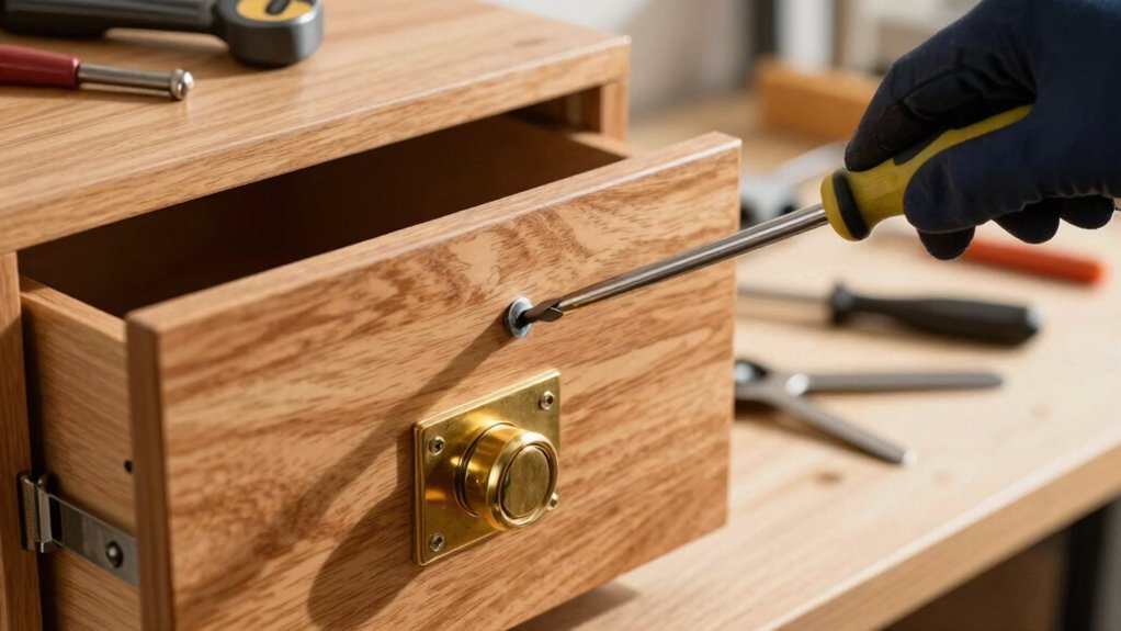
How do you keep the cabinet stable while you detach the back panel? Position the cabinet on a level, sturdy surface and place cardboard underneath to protect the panel and frame. Wear gloves for safety and keep the door closed to preserve structural integrity. Using a flat‑head screwdriver, pry the front edge of the opener‑lever cover, then pull the triangular piece at the top rear with your fingers. Work sequentially around the edges, applying gentle outward pressure to release snap‑fit clips without cracking plastic retainers. Begin panel removal from the bottom, pulling straight outward in half‑inch increments until all clips release. Lift the panel upward by its edges, set it on padding, and maintain ergonomics by keeping the panel close to your body to avoid strain. Ensure the safe’s door removal is performed before moving the cabinet to prevent damage. Familiarize yourself with the lock release mechanism to avoid accidental discharge. Biometric lock systems can provide an extra layer of security for firearms. Follow the panel replacement steps to ensure a secure and lasting installation.
Extract Old Stack‑On Lock Mechanism & Mouse‑Trap Lever
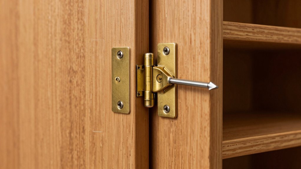
Once you’ve removed the back panel, the next step is to extract the old stack‑on lock mechanism and the mouse‑trap lever; start by loosening the retaining nut with a crescent wrench, slide it off together with the two washers, and then pull the lock cylinder straight out, allowing the square‑flat rod to disengage from the latch and freeing the lever that will drop the locking bars. Perform lever rod removal in one smooth motion, watching the rod slide cleanly out of the square‑flat recess. Inspect the interior for any retained debris, then verify Lever alignment verification by confirming the lever sits flush against the latch housing. Guarantee the D‑shaped stud on the new lock will mate correctly before proceeding. This methodical extraction prepares the cabinet for the upcoming installation phase. The original lock requires a 90‑degree turn for operation 90‑degree turn. Ensure you have a cable cutter on hand to trim any excess wiring that may interfere with the new lock installation. Selecting a lock with a high security rating can significantly improve protection against forced entry. Durable lock mechanisms are essential for long‑term reliability in high‑traffic environments.
Install New Front Plate, Keypad & Solenoid
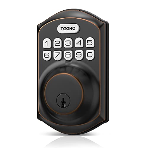
After the old lock mechanism and mouse‑trap lever are removed, you can begin installing the new front plate, keypad, and solenoid. First, verify material compatibility; the zinc‑alloy black round keypad panel must match the door’s existing design design. Press the old keypad tab counter‑clockwise, pop off the SG tab sticker, and unscrew the front plate after removing protective stickers and tabs. Detach the solenoid by unscrewing screws under the SG tab, removing the second battery‑housing screw, and unplugging control wires. Insert batteries into the new keypad housing, secure the release tab, and mount the front plate onto the door’s mounting points, aligning holes for a flush fit. Tighten all screws, plug control wires into the new solenoid terminals, route them behind the top screw, and guarantee the capacitor aligns correctly before testing activation. The back panel slides out to expose the lock mechanism, allowing easy access to the battery compartment. properly‑aligned holes ensure a secure and smooth installation. Choosing a lock with a tamper‑resistant design further enhances security for both residential and commercial cabinets. This type of cabinet is considered furniture because it is a movable object designed for storage.

Passcode Entry: This keypad lock offers 20 access codes for family use and a temporary code for single-use guest entry

Passcode Entry: This keypad lock offers 20 access codes for family use and a temporary code for single-use guest entry
Passcode Entry: This keypad lock offers 20 access codes for family use and a temporary code for single-use guest entry
Connect Power, Reset Cable & Motherboard for Stack‑On Lock
When you connect the power, reset cable, and motherboard, start by securing the battery compartment inside the safe door, making sure the wires are positioned without pinching. Route the battery leads to the lock body, then attach the red reset cable to the PCB’s designated connector, keeping tension slack. Align the motherboard with the interior mounting tabs, bend the tabs over, and verify that the light behind the board confirms proper placement. Tighten the set screws on the battery cover to lock the wires in place. Apply power routing by confirming the yellow panel light illuminates, indicating motherboard activation. Finally, initiate a firmware update via the keypad to synchronize the lockset assembly with the factory preset code, then test solenoid response before closing the door. Ensure the lock is in the unlocked position before proceeding. Regularly inspect the cabinet for loose hinges and tighten any screws to prevent hardware failure. High‑quality locks are essential for maximizing protection against unauthorized entry.

Note: This product is a set of combination products, not detachable for use, please remove all your old parts and adopt all our new parts to work properly
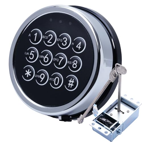
COMPLETE SAFE LOCK SETS:The lock consists of a panel, a solenoid, 2 override keys,a reset line (red) and a motherboard (PCB), operated by an electromagnetic locking mechanism, more confidential!

This F PANEL adapter solve compatibility issues by converting modern motherboard header into separate 2pin connector for power and reset switches, enabling seamless connection to older or computer cases without modifications.
Program Stack‑On Factory Code & Set Custom Access Code
How do you program a new personal code after entering the factory preset? First, press the red reset button inside the door, remove the cap, and press once. The yellow light will stay on and all buttons flash, giving you a five‑second window. Enter the factory code 1‑5‑9‑[#] while the door is unlocked; the handle must turn clockwise within five seconds. When the yellow light activates, type your **3‑8‑digit personal code using the keypad mapping, then press *. Two beeps (or a single beep on some models) confirm recording. After programming, replace the reset button cap. The factory reset sequence guarantees the lock returns to its default state before you set the custom access code. A small paper clip can be used to open the safe quickly. Parallel wheel replacement can be performed using a screwdriver and a wrench. Choosing a lock with a high security rating helps ensure the cabinet remains protected against tampering. Properly tighten the hinge screws** to maintain alignment and prevent future loosening.

Note: This product is a set of combination products, please remove all your old parts and adopt all our new parts to work properly (PLEASE BE SURE TO USE 9V ALKALINE BATTERY)

Complete Key Set Included: Comes with 2 keys for convenient access and backup security

Direct Replacement: Armstrong Replacement Lock is designed specifically for current models of Stack-On and Sentinel gun cabinets, providing a seamless fit with an upgraded brass finish.
Verify Unlock, Lock & Timeout Functions
Now that the personal code is programmed, you need to confirm that the lock’s core functions—unlock, lock, and timeout—behave as specified. Begin unlock verification by entering the factory code or key, ensuring the bolt retracts fully without resistance and the handle turns smoothly. Listen for the audible click or observe the indicator light, then repeat with several code entries to guarantee consistent response. For lock verification, close the door firmly, input an invalid code, and confirm the 3‑point or 4‑way locking engages securely; pull the handle to verify bolt extension and check alignment for a tight seal. Conduct timeout testing by entering incorrect codes repeatedly, noting the 5‑15‑minute lockout period, attempting entry during the timeout, and confirming normal operation resumes after the interval. Repeat to ensure reliable timing. The cabinet’s three‑point lock system provides added security when properly verified. Durable lock materials are essential for long‑term performance in high‑traffic environments.
Troubleshoot Common Issues & Verify Full Security
If the lock isn’t responding as expected, start by checking the battery, then move on to the keypad wiring and mechanical components. Verify battery lifespan by noting the installation date; replace any 9‑volt cell older than twelve months. Open the compartment by pressing the bottom and turning counter‑clockwise, then install a fresh battery. Conduct keypad troubleshooting: inspect the thin wiring harness for loose connections, reseat any slack nuts, and test each key with a multimeter. If the keypad remains dead, use the master key through the bottom hole to disengage the electronic latch and confirm mechanical lock movement. Finally, rotate the cabinet back to relieve rust‑induced binding, apply lock‑lube, and cycle the lock open and closed to guarantee full security. Keypad failure can occur after relocation, as reported by a customer whose safe was three years old.

AVAILABLE SIZES: Duracell Coppertop alkaline batteries are available in C batteries, D batteries, 9V batteries, AA & AAA batteries

Good Quality: The hard shell battery button connector is made of solid plastic and metal. The solid plastic is solid and not easy to break. The metal contact performance is good. The cable tail is easy to solder by immersion tin

1 pack of Energizer Ultimate Lithium 9V Batteries